Failing to use the 5 Whys risks a recurrence of the failure – the corrective action may only address symptoms of the failure. Each time a cause is identified, the 5 Whys should be used to dig deeper to find the true underling cause of the failure.

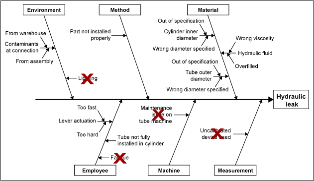
Had the 5 Whys not been used, then the employee may have been retrained, but the same employee or somebody else may have made the same or a different mistake due to the poor lighting. In this example, the use of 5 Whys led to the true cause of the failure – the light bulbs burned out. For example, the branch may end up as: material → part not installed → employee skipped operation → work environment too dark → poor lighting → light bulbs burned out. The Ishikawa diagram should be expanded each time 5 Whys is used. The lighting may be a contributing cause, but it should not be the first one investigated. If a part is not correctly installed, then use the 5 Whys on that part of the Ishikawa diagram for investigation. Simply investigating the lighting could take time and resources away from the investigation so the first step would be to see if a part is installed.Ĭauses of a part not being installed can be listed as sub-branches, but the priority should be on determining if the part was installed or not. Therefore, the part not properly installed would be listed in the Ishikawa diagram. In this example, lighting could cause an employee to make a mistake resulting in a part not properly installed. Instead, the result of bad lighting should be listed and then empirically investigated. For example, “lighting” is a typical example under “environment” however, it is seldom clear how lighting could lead to the failure. Figure 1: Ishikawa Diagram How Did the Failure Happen?Įlements in the Ishikawa diagram should be able to explain how the failure happened. Hypotheses that have been investigated can also be marked on the Ishikawa diagram to quickly show that they are not the cause of the failure (Figure 1). It serves to quickly communicate these hypotheses to team members, customers and management. An Ishikawa diagram should be viewed as a graphical depiction of hypotheses that could explain the failure under investigation. A good problem statement would be: “Customer X reports 2 shafts with part numbers 54635v4 found in customer’s assembly department with length 14.5 +/-2 mm measuring 14.12 mm and 14.11 mm.” Create an Ishikawa DiagramĪn Ishikawa (or fishbone) diagram should be created once the problem statement is written and data has been collected. For example, a problem statement may start as, “Customer X reports Product A does not work.” The rest of the problem statement would then clarify what “does not work” means in technical terms based upon the available data or evidence. The customer’s description does not need to be correct it should reflect the customer’s words and be clear that it is a quote and not an observation.

The customer’s description of the failure.The problem statement should include all of the factual details available at the start of the investigation including: Although critical for starting an RCA, the problem statement is often overlooked, too simple or not well thought out. Once a problem-solving team has been formed, the first step in an RCA is to create a problem statement. This is not necessarily wrong, but often the ideas listed do not clearly contribute to the failure under investigation. Often, failure investigations begin with brainstorming possible causes and listing them in an Ishikawa diagram. RCA can progress more quickly and effectively by pairing an Ishikawa diagram with the scientific method in the form of the well-known plan-do-check-act (PDCA) cycle to empirically investigate the failure. Root cause analysis (RCA) is a way of identifying the underlying source of a process or product failure so that the right solution can be identified.


 0 kommentar(er)
